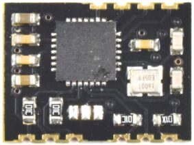
This Development Kit comes as easy to build DIY Soldering Kit and includes 1 Module EverSet ES100-MOD and 1 Carrier Board.
CANADUINO ES100 Atomic Clock Receiver ADK features a 4 line, 20 characters LCD, 2 fine-tuned 60kHz antennas with antenna holder, a real-time clock (RTC) chip with a backup battery, and a pre-programmed, Arduino compatible ATmega328 Microcontroller already loaded with a demo program.
The Development Kit works as a high-precision atomic clock out of the box (after assembling). The display shows all available information like time, date, the current status of DST and next DST status change. It also shows which antenna was used for synchronizing (1 or 2) and how many trials it took to successfully receive and decode a complete frame.
Note: Regardless basic functions being offered with the included demo code, this is NOT meant to be a flawlessly developed wall clock for daily use! It is meant to be a tool for product designer and software engineers to build projects and devices using the ES100 receiver chip. We had people returning the kit because “the buttons are not working”. Please understand the purpose of an ADK before you are disappointed. The provided code demonstrates basic functionality and is not perfectly debugged as well. Building a perfect application is YOUR job.
Specifications:
– Platform: Arduino UNO compatible
– Processor: ATmega328P-PU, 16MHz (5V)
– Power Supply: 5V, <100mA
– RTC: DS1307 with backup battery CR1220
– I/O: 5 x GPIO, 4 x analog in, 1 x serial RX/TX, 1 x ICSP
– Buttons: 1 x reset, 3 x user definable
– Display: 4 x 20 character LCD with backlight (5V)
– On-Board 3.3V voltage regulator for ES100MOD
– On-Board Level Shifter 3.3-5V
The ES100 ADK offers a 1×6 female header to connect with an ES100-MOD Carrier Board and a spot for an ES100-MOD Module without Carrier Board (direct PCB-to-PCB connection).
Interesting projects making use of the ES100 WWVB receiver module:
Check out Keith Greiner’s page “WWVB Receiver with Arduino” for in-depth details about his ES100 project.
Substitute parts in DIY soldering kits:
Sometimes, we can’t source the exact parts as listed in the documentation. Then we will ship the kit with substitutes close enough to guarantee proper function. To avoid mistakes, install the exact matching parts first, and then see what is left and match these parts to the empty spaces on your PCB. This way, you avoid installing the wrong parts by mistake.
3 reviews for EverSet ES100 ADK for Atomic Clock Applications (DIY kit)
Rated 5 out of 5
ve7gcr (verified owner)–
Absolutely great kit, definitely a five star package. More than an Application Development Kit, a Skills Development kit as well. Built my first superheterodyne transmitter/receiver a few years back when tubes and discrete components were the parts of choice. The ES100 kit has taken me from the “knob and tube” era to the IC world of Arduino.
It took a few days (a few hours each day) to assemble. Documents, schematics and pictures were very easy to follow. Powered the unit up with a breadboard power supply, and got a signal after 286 interrupts (overnight) in my radio room. Swapped the 328PU in the ES100 with one in a UNO. Made some basic sketch changes (time zone and refresh time) and replaced the processor. Plugged in a 9 volt battery to the power supply and packed the unit over to a south facing window. Sync’s in 2 interrupts. Checked Google maps, and WWVB transmitter is 1,780 km SSE. I regularly use the 2.5, 5, 10, 15 & 20 MHz signals to check signal strength, antenna and tuner. Next step, try ICSP to make changes to the sketch in the 328PU.
Started by searching the internet only to find a million different ways to setup an ISP programmer. Settled on one that seemed to make sense. Built the circuit, putting in a capacitor between the ground and reset pins, double checked the wiring, and set up the blink sketch to transfer between two UNO’s via the ICPS pins, clicked upload, and voila , lights flashed and two instant bricks were created (salvaged them later). Bootloaders were scrambled (without toast). Biggest stumbling block was the boards on my 1.8.2 version of the IDE were not up to date (using Windows 7). NOTE: the Arduino reference for ISP is correct, but misleading, the bootloader part is not needed to do a sketch upload.
With my UNO’s out of commission, a NANO became my ISP programmer and had robbed another UNO for the 328PU, got the 328PU programmed using the ICSP pins. With a dud 328PU in the ES100, the total current draw was just over 50ma, so minor care is needed to supply the ES100 so no GPIO should exceed 40ma or 250ma for the programmer.
Next part of the Application Development; UART communications to another device, first by wire, then using wifi to sync data loggers and some home automation projects.
Would recommend a clear straightforward step by step for the Arduino ISP, with no discussion about bootloaders. A pdf document with the kit documentation would be useful for us novice Arduino developers. Live and learn.
Definitely ⭐️⭐️⭐️⭐️⭐️…….
Greg R VE7GCR, BC Canada.
Rated 5 out of 5
wa3etd (verified owner)–
Outstanding kit! Assembly is painless if one has basic soldering skills and a good soldering station.
My only nit is that several of the caps provided were alternately sourced and didn’t match the footprint on the PCB – minor.
Note that the clock does not immediately start timekeeping, even with a good 60 kHz signal. The initial display presents two lines of info and incorrect time. My clock took about 5 minutes to lock, which allows all data to be presented.
I highly recommend this kit – the main PCB is high quality and silkscreened.
Rated 5 out of 5
wa3etd (verified owner)–
This is my second “review” of this outstanding module. Regarding the provided demo program, I have comments that can be ignored by anyone not interested in modding the demo. Much of the following was discovered when porting the code to an Arduino DUE (3.3V I/O), eliminates the need for three level converters The following applies to the stock demo program.
1. Any additional variable added will be corrupted by an array dimensioned incorrectly.
In char * getISODateStr()
{
static char result[21]; // Was 19, which is a bug. Array was too small. FIX THIS
———————————————————–
2. Scrolling display flickers when viewing off boresight. The three scrolling rows are precleared every cycle by writing
20 spaces in each row prior to the desired data. LCD writes are expensively slow. The fix is to eliminate the
clearing – eliminate the clearLine(20); statement at each case. Then, pad each of the optional scrolling fields to
exactly 20 positions. For example, (snip)
case B11:
lcd.print(“Pos. LS this month “); // pad to 20
break;
—————————————————–
3. Although code is present, the program will never update the RTC after the initial signal capture. This is due to the
actual TOD not being updated for the comparison to the user provided update time. This can be cured by
capturing the actual time each cycle in function char * getISODateStr() and using that for the update test.
——————————————————————–
4. Note that the three pushbuttons are incorrectly called out on the silkscreen. The schematic is correct, the labeling
is incorrect.
As mentioned, the demo ported to the DUE with no issues. I used a DS3231 clock module instead of the ‘1307, and a
I2C liquid crystal display to save interconnects. I2C LCDs are even slower that direct wired displays, which emphasized the scroll flicker – totally resolved by the above fix.
Hopefully this will help some, and encourage others to “get into the code”. Fun project all around!
Only logged in customers who have purchased this product may leave a review.


ve7gcr (verified owner) –
Absolutely great kit, definitely a five star package. More than an Application Development Kit, a Skills Development kit as well. Built my first superheterodyne transmitter/receiver a few years back when tubes and discrete components were the parts of choice. The ES100 kit has taken me from the “knob and tube” era to the IC world of Arduino.
It took a few days (a few hours each day) to assemble. Documents, schematics and pictures were very easy to follow. Powered the unit up with a breadboard power supply, and got a signal after 286 interrupts (overnight) in my radio room. Swapped the 328PU in the ES100 with one in a UNO. Made some basic sketch changes (time zone and refresh time) and replaced the processor. Plugged in a 9 volt battery to the power supply and packed the unit over to a south facing window. Sync’s in 2 interrupts. Checked Google maps, and WWVB transmitter is 1,780 km SSE. I regularly use the 2.5, 5, 10, 15 & 20 MHz signals to check signal strength, antenna and tuner. Next step, try ICSP to make changes to the sketch in the 328PU.
Started by searching the internet only to find a million different ways to setup an ISP programmer. Settled on one that seemed to make sense. Built the circuit, putting in a capacitor between the ground and reset pins, double checked the wiring, and set up the blink sketch to transfer between two UNO’s via the ICPS pins, clicked upload, and voila , lights flashed and two instant bricks were created (salvaged them later). Bootloaders were scrambled (without toast). Biggest stumbling block was the boards on my 1.8.2 version of the IDE were not up to date (using Windows 7). NOTE: the Arduino reference for ISP is correct, but misleading, the bootloader part is not needed to do a sketch upload.
With my UNO’s out of commission, a NANO became my ISP programmer and had robbed another UNO for the 328PU, got the 328PU programmed using the ICSP pins. With a dud 328PU in the ES100, the total current draw was just over 50ma, so minor care is needed to supply the ES100 so no GPIO should exceed 40ma or 250ma for the programmer.
Next part of the Application Development; UART communications to another device, first by wire, then using wifi to sync data loggers and some home automation projects.
Would recommend a clear straightforward step by step for the Arduino ISP, with no discussion about bootloaders. A pdf document with the kit documentation would be useful for us novice Arduino developers. Live and learn.
Definitely ⭐️⭐️⭐️⭐️⭐️…….
Greg R VE7GCR, BC Canada.
wa3etd (verified owner) –
Outstanding kit! Assembly is painless if one has basic soldering skills and a good soldering station.
My only nit is that several of the caps provided were alternately sourced and didn’t match the footprint on the PCB – minor.
Note that the clock does not immediately start timekeeping, even with a good 60 kHz signal. The initial display presents two lines of info and incorrect time. My clock took about 5 minutes to lock, which allows all data to be presented.
I highly recommend this kit – the main PCB is high quality and silkscreened.
wa3etd (verified owner) –
This is my second “review” of this outstanding module. Regarding the provided demo program, I have comments that can be ignored by anyone not interested in modding the demo. Much of the following was discovered when porting the code to an Arduino DUE (3.3V I/O), eliminates the need for three level converters The following applies to the stock demo program.
1. Any additional variable added will be corrupted by an array dimensioned incorrectly.
In char * getISODateStr()
{
static char result[21]; // Was 19, which is a bug. Array was too small. FIX THIS
———————————————————–
2. Scrolling display flickers when viewing off boresight. The three scrolling rows are precleared every cycle by writing
20 spaces in each row prior to the desired data. LCD writes are expensively slow. The fix is to eliminate the
clearing – eliminate the clearLine(20); statement at each case. Then, pad each of the optional scrolling fields to
exactly 20 positions. For example, (snip)
case B11:
lcd.print(“Pos. LS this month “); // pad to 20
break;
—————————————————–
3. Although code is present, the program will never update the RTC after the initial signal capture. This is due to the
actual TOD not being updated for the comparison to the user provided update time. This can be cured by
capturing the actual time each cycle in function char * getISODateStr() and using that for the update test.
——————————————————————–
4. Note that the three pushbuttons are incorrectly called out on the silkscreen. The schematic is correct, the labeling
is incorrect.
As mentioned, the demo ported to the DUE with no issues. I used a DS3231 clock module instead of the ‘1307, and a
I2C liquid crystal display to save interconnects. I2C LCDs are even slower that direct wired displays, which emphasized the scroll flicker – totally resolved by the above fix.
Hopefully this will help some, and encourage others to “get into the code”. Fun project all around!