


Application Development Kit for EverSet ES100-MOD Atomic Clock Receiver


CAD 59.98
| Quantity | 3 - 9 | CAD 53.98 |
| Quantity | 10 - 24 | CAD 52.48 |
| Quantity | 25 + | CAD 50.98 |
- Description
- Reviews (11)
Description
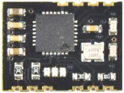
We created an ADK for the new EverSet ES100MOD Atomic Clock Receiver Module.
This Development Kit comes as easy to build DIY Soldering Kit and includes 1 Module EverSet ES100-MOD and 1 Carrier Board.
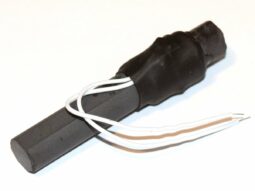
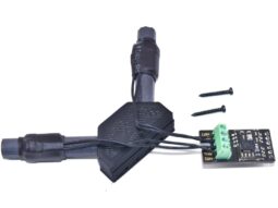
CANADUINO EverSet ES100 Application Development Kit features a 4 line, 20 characters LCD, 2 fine-tuned 60kHz antennas with antenna holder, a real-time clock (RTC) chip with a backup battery, and a pre-programmed, Arduino compatible ATmega328 Microcontroller already loaded with a demo program.
The Development Kit works as a high-precision atomic clock out of the box (after assembling). The display shows all available information like time, date, the current status of DST and next DST status change. It also shows which antenna was used for synchronizing (1 or 2) and how many trials it took to successfully receive and decode a complete frame.
Note: Regardless basic functions being offered with the included demo code, this is NOT meant to be a flawlessly developed wall clock for daily use! It is meant to be a tool for product designer and software engineers to build projects and devices using the ES100 receiver chip. We had people returning the kit because “the buttons are not working”. Please understand the purpose of an ADK before you are disappointed.
Specifications:
– Platform: Arduino UNO compatible
– Processor: ATmega328P-PU, 16MHz (5V)
– Power Supply: 5V, <100mA
– RTC: DS1307 with backup battery CR1220
– I/O: 5 x GPIO, 4 x analog in, 1 x serial RX/TX, 1 x ICSP
– Buttons: 1 x reset, 3 x user definable
– Display: 4 x 20 character LCD with backlight (5V)
– On-Board 3.3V voltage regulator for ES100MOD
– On-Board Level Shifter 3.3-5V
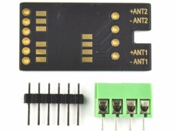
The board offers a 1×6 female header to connect with an ES100-MOD Carrier Board and a spot for an ES100-MOD Module without Carrier Board (direct PCB-to-PCB connection).
Interesting projects making use of the ES100 WWVB receiver module:
ES100 with Raspberry Pi and Python by Martin Levy
ES100 WWVB reference clock by fiorenzo1963
ES100 WWVB receiver with Arduino DUE (ARM Cortex-M3)
Code and document downloads:
Manual and Assembling Instructions (Document V1.0)
PCB Position Print
Test Code (Arduino) with serial output
ES100-MOD Datasheet (Document Version 1.0)
Arduino demo code V1.2 (including ES100 Arduino library V1.1)
Substitute parts in DIY soldering kits:
Sometimes, we can’t source the exact parts as listed in the documentation. Then we will ship the kit with substitutes close enough to guarantee proper function. To avoid mistakes, install the exact matching parts first, and then see what is left and match these parts to the empty spaces on your PCB. This way, you avoid installing the wrong parts by mistake.
11 reviews for Application Development Kit for EverSet ES100-MOD Atomic Clock Receiver
Add a review
You must be logged in to post a review.
Related products
-
 Quick View
 -
 Quick View
 -
 Quick View
 -
 Quick View


John C. Westmoreland, P.E. (verified owner) –
To ES100-MOD WWVB BPSK Dev Kit Customers,
My unit has been running most of the day today. Even without instructions per se – the schematics, BOM, and layout diagram plus the pictures on the site here are enough to build the unit with. The most time consuming part for me was bending the TH parts – namely resistors, so they fit nicely. The only other difficulty was getting the antenna holder to correctly hold both antennas – but that’s not that hard really. The default app that was loaded booted right up – I took some pics to post here – but don’t see a way to attach. Overall, it was pretty easy to put together and not too many parts as to make you confused without detailed assembly instructions.
Regards,
John Westmoreland
John C. Westmoreland, P.E. (verified owner) –
To add to the top review –
I am powering the unit with a Li-Ion batter pack – works great. (Maybe add that to the review?) (And, is there a way to add a picture of the built unit?)
Regards/Thanks,
John Westmoreland
UNIVERSAL-SOLDER –
Thank you for the review. Unfortunately, an option to add pictures to reviews is not yet available.
John C. Westmoreland, P.E. (verified owner) –
Hello Everyone,
Regarding the assembly instructions draft –
Just a quick note regarding the I2C pull-ups – the main board provides those – R5 and R9 – both 10K – so, it’s unnecessary to solder the jumpers on the ES100 MOD adapter board.
Best Regards,
John Westmoreland
UNIVERSAL-SOLDER –
Thank you, you are right. We will correct this.
benjamin.hall (verified owner) –
This is a great kit that works really well and I am very pleased!
My kit arrived about a week before the promised arrival date which was a nice surprise given that COVID-19 is causing havoc with shipping everywhere. It was very nicely packed in anti-static bags with the components grouped together logically. The printed circuit board is extremely high quality and it’s clear a lot of care when into it’s design. Using the online assembly instructions, I put it together in about two hours (minus a break for lunch) and everything went together mostly smoothly, with a couple of errors on my part that were easily fixed. After about 10 minutes of being powered on, it had received time from WWVB successfully. This is rather amazing, as my lab is filled with RF hash and noise…and it’s being powered by what I suspect is a very noisy USB “wall wart” type of power supply.
I am very happy with my purchase. Given how quickly it arrived, I’ll likely be buying more electronics from Universal Solder in the future.
Thanks much and 73,
Ben Hall, KD5BYB
UNIVERSAL-SOLDER –
Thank you for the nice review. I am glad you like that kit.
73s
Volker Forster
tomeschulz (verified owner) –
I got the kit and assembled it fairly quickly. I did not initially install the battery. I powered it up and the display was completely blank until I adjusted the contrast. I had not expected that a misadjusted contrast would result in a completely blank display. It acquired the time and worked. Later I installed the battery and found that it would not work with the battery installed. After much troubleshooting, I found that my adjustable power supply was misadjusted and was putting out 4.8 volts. Running it up to 5 volts fixed the problem. With the 0.3 volt drop of the diode in series with the power supply, the real time chip had been getting only 4.5 volts. It seems that it needs more than that to switch from battery mode to powered up mode.
I find that the clock will re-sync the time every day at 4 AM universal time.
Stuart Kramer (verified owner) –
This is a great kit, pretty straightforward and fun to assemble — though it took me double that of another commenter— and I still had some bad solder joints! It’s running well from an old USB AC charger. I have no particular need or application in mind, but I’m thinking about connecting it to my Fibonacci Clock which updates its display in 5 minute increments, as a reminder of the distinction between accuracy and precision 😉 Universal Solder Rules!
david.haycock (verified owner) –
This is a great project. The board is very well laid out and assembly is easy. It worked first time with zero issues. Mechanically it is very sound too.
The receiver works very well even here in distant Washington State. In contrast to the old style WWVB receivers this receiver syncs very reliably. It varies from day to day but on some days I have seen it sync up anytime of day or night. Although it is a minor niggle I would have liked to see a coaxial power
connector on the board for 5V, or a couple of bare solder pads. The header isn’t a great way to put power into it.
Although it is not proven to be an issue I should note that the driver for the RTC is for a DS3231 not the DS1307 used on the board. It works OK since the registers are compatible, but the DS3231 driver sets the I2C rate to 400kHz and the DS1307 is specd for 100kHz. Apparently the DS1307 is OK with that.
UNIVERSAL-SOLDER –
Thank you very much for your review. Please let me just clarify some small details:
The DS3231 library works perfectly for the DS1307. But it is entirely up to you to use different libraries for display, communication, memory card or RTC. This is an application development kit, not a consumer product. The great advantage of providing Arduino compatibility enables even unskilled electronics novices to create something that works with ease and then start from there to develop their own clock project.
The headers are sufficient to provide power to the module under lab conditions when creating and testing your own code. The headers are of course not intended to supply power to a clock someone wants to put up in their living room.
I hope it is understood that this is a development tool to develop products. It is not meant to be a consumer product intended for daily use for example as an alarm clock.
david.haycock (verified owner) –
I would not have given this a 5 star rating had I not found it to be an excellent product. My comments about the connector and driver were intended to be suggestions for further improvements not a criticism. Yes I appreciate it is a development board, I have used many different ones in the past and this is probably the best of them all. I have made good use of the extra switches provided and already have learned a lot about the WWVB PSK performance most of which based on observations of it running in continuous update mode. WWVB PSK is a far better performer than the legacy AM/PWM system and highly recommended for anyone who has had issues with syncing to that old format.
Alan Rothenbush –
I had a wee bit of a problem with mine, in that after carefully soldering it up, making all the usual checks and applying power, nada. Nothing on the LCD display. I was pretty sure that soldering wasn’t the problem; my first electronics kit was an Eico tube scope, built almost 60 years ago, and I’ve been an electronics guy ever since. I know how to solder.
My first guess was that the 328 uP wasn’t programmed. I found an Arduino Nano, converted it to an ISP, downloaded and ran successfully a “Hello World” . This convinced me the Nano as ISP worked. I then downloaded the Everset code from this site and .. still nada.
Using the LCD as a debugging tool, I added LCD.print (“something”) lines throughout the code.
The execution seemed to stop right after attempting to communicate with the DS1307 clock chip.
Closer examination showed that there was no 32 KHz oscillation at the crystal pins, so I swapped in a different crystal. No oscillation. I swapped in another DS1307 I was lucky enough to have in the parts bin. No oscillation. Tried two more 32 KHz crystals. No oscillation. Did all of the above with the original DS1307. No oscillation. Breadboarded the DS1307 because MAYBE there was something wrong the PCB. No oscillation, from either DS1307, with all xtals.
Got frustrated. I have a few DS3231 boards around with the four key lines broken out to a header, so I soldered one in place of the DS1307.
Everything is good!
SOMEHOW, the DS1307 in the kit and the one I’ve had for years, and/or the 32 KHz xtal and the xtals I’ve had for years, are bad. I don’t know what the odds of that are, but I don’t care. I can now walk over to my bench and learn the time; I no longer need to go to all the trouble of pulling up my sleeve and checking the watch on my arm. 🙂
Next step .. figure out how to add an ES100 to a clock I made a while back, using a PIC uController and a bunch of Nixie tubes out of an old counter. Currently, the time is set by pushbuttons, and we can’t have that, even if the buttons are only pressed every few years!
If it works, and it should, it will be kinda cool to learn time from those old tubes and an atomic reference signal from more than a thousand miles away.
Can’t give it 5 stars for the weird DS1307 issue, but can say I’d buy it again.
Alan Rothenbush –
Well, I “spoke” a little too soon when submitting my previous review. I’ll still give the kit 4 stars, nothing has changed on that front. But I have not, as yet, been able to retrieve the time. I suspect I’m just too far away with too many mountains in between. (If there’s a way to read signal strength, I don’t know what it is.)
I do get reception, as the ES100 does generate interrupts, but the interrupt result is always “4”, i.e., incomplete transmission. This occurs even when the device is placed on the top floor in front of an open south facing window.
So I guess it’s back to NTP running on an ESP8266.
The atomic clock has sure been fun to play with though!
buttertoffeemoon –
Alan, the ES100 with the dual-antenna is the best way to receive WWVB. There is no better receiver technology. But if you have a lot of “garbage” in the air, or maybe even n your power supply, then the receiver will catch this as well. The downside of any super-sensitive receiver is that it also is sensitive to anything else that’s in the air. From switching power supplies, PWM TV backlight, microwave, smartphone, wireless thermometers and so on. The ES100 receiver was successfully tested in Greenland, over almost 5000km distance. BTW, we recommend not to power it from a 5V USB charger or something similar cheap. A battery is the best option or a better bench PSU.
ve7gcr (verified owner) –
Absolutely great kit, definitely a five star package. More than an Application Development Kit, a Skills Development kit as well. Built my first superheterodyne transmitter/receiver a few years back when tubes and discrete components were the parts of choice. The ES100 kit has taken me from the “knob and tube” era to the IC world of Arduino.
It took a few days (a few hours each day) to assemble. Documents, schematics and pictures were very easy to follow. Powered the unit up with a breadboard power supply, and got a signal after 286 interrupts (overnight) in my radio room. Swapped the 328PU in the ES100 with one in a UNO. Made some basic sketch changes (time zone and refresh time) and replaced the processor. Plugged in a 9 volt battery to the power supply and packed the unit over to a south facing window. Sync’s in 2 interrupts. Checked Google maps, and WWVB transmitter is 1,780 km SSE. I regularly use the 2.5, 5, 10, 15 & 20 MHz signals to check signal strength, antenna and tuner. Next step, try ICSP to make changes to the sketch in the 328PU.
Started by searching the internet only to find a million different ways to setup an ISP programmer. Settled on one that seemed to make sense. Built the circuit, putting in a capacitor between the ground and reset pins, double checked the wiring, and set up the blink sketch to transfer between two UNO’s via the ICPS pins, clicked upload, and voila , lights flashed and two instant bricks were created (salvaged them later). Bootloaders were scrambled (without toast). Biggest stumbling block was the boards on my 1.8.2 version of the IDE were not up to date (using Windows 7). NOTE: the Arduino reference for ISP is correct, but misleading, the bootloader part is not needed to do a sketch upload.
With my UNO’s out of commission, a NANO became my ISP programmer and had robbed another UNO for the 328PU, got the 328PU programmed using the ICSP pins. With a dud 328PU in the ES100, the total current draw was just over 50ma, so minor care is needed to supply the ES100 so no GPIO should exceed 40ma or 250ma for the programmer.
Next part of the Application Development; UART communications to another device, first by wire, then using wifi to sync data loggers and some home automation projects.
Would recommend a clear straightforward step by step for the Arduino ISP, with no discussion about bootloaders. A pdf document with the kit documentation would be useful for us novice Arduino developers. Live and learn.
Definitely ⭐️⭐️⭐️⭐️⭐️…….
Greg R VE7GCR, BC Canada.