


Electronic Education and Troubleshooting Project “The broken code lock” DIY kit


CAD 15.97
| Need more than we have? Order now, we will ship when back in stock. Lead time about 2-3 weeks. See our backorder policy. |
| Quantity | 3 - 9 | CAD 14.37 |
| Quantity | 10 - 24 | CAD 13.97 |
| Quantity | 25 + | CAD 13.57 |
- Description
Description
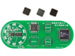
Electronic Education and Troubleshooting Project “The broken code lock” is a DIY soldering kit especially developed for students and to build basic skills for electronic beginners.
The module requires 12V AC or DC input voltage (standard 2.1/5.5mm barrel connector).
When you finished assembling the kit following the schematic, you must adjust R4 to achieve a voltage of 9V on TP1. Not possible? Find out why, and fix it using the spare parts in the bag.
After adjusting the voltage, you need to decrypt the code by reading and understanding the schematic and the CD4017 datasheet. After entering the code, the LED “decrypted” will tell about your success.
Hint: The code number is connected to Canadian history.
The next step requires you to read the datasheets of the other two integrated circuits, to understand their function, and to use your fresh knowledge to unlock the door (the LED “unlocked” will show your success). This is a bit tricky, but it wouldn’t be fun without the challenge.
Hint: On your way to find out how to unlock the door, you will discover a problem with the PCB that needs to be fixed.
Depending on your skill level and experience, you can finish the entire project within 1 hour (great skills) or 1 day (novice).
Additional topics for teachers:
– discuss the function of D1-D4 and C1
– discuss the purpose of D6-D12
– compare the waveforms on TP3 and TP4 and explain the function of R12, R14, C10 and C11
– discuss the reason for D14 being connected to the relay
Datasheets required for the project:
LM567 Tone Decoder
NE555 Precision Timer
CD4017 Decade Counter
Related products
-
 Quick View
 -
 Quick View
 -
 Quick View


